cyclogram
Ball screw, belt drive and load terms
The words of step 2 — the ball screw, the belt drive, the gearbox and the load that moves — each with what it means, its unit, what is typical, and a short animation. Try any of them in the calculator.
Actuator Screw lead Screw diameter Root diameter Length between bearings Screw efficiency Supports Nut preload Preload friction Coupling inertia Screw inertia Pulley pitch diameter Belt mass Pulley width Pulley material Pulley inertia Belt efficiency Allowable belt force The load, part by part Gearbox Gear ratio Gearbox efficiency Gearbox inertia
Actuator
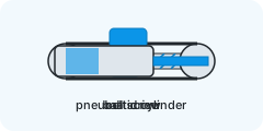
The mechanism that turns the motor's torque into the move — or, for a cylinder, the air that does it instead.
- Typical
- ball screw for precision, belt for long fast strokes, rack for long travel, rotary table for indexing, cylinder for a two-position move
Each type has its own fields. The ball screw and the belt drive are complete today; the others follow.
Screw lead
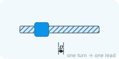
How far the nut travels when the screw turns once.
- Unit
- mm
- Typical
- 5 – 20 mm; 25 – 40 mm for fast axes
A longer lead gives more speed per motor turn and less thrust per unit of torque — and a lower screw speed for the same table speed.
Screw diameter
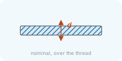
The nominal (outer) diameter of the screw shaft.
- Unit
- mm
- Typical
- 12 – 25 mm for small axes, 32 – 50 mm for machine tables
It sets the screw's own inertia, its stiffness, its critical speed and the D·N value the nut's balls can take.
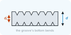
Root diameter
The diameter at the bottom of the thread groove — the shaft that actually bends.
- Unit
- mm
- Typical
- about 0.8 – 0.9 × the nominal diameter
It is what the critical-speed formula uses. Leave it blank and the page takes 0.85 × the nominal diameter; the catalogue has the exact figure.
Length between bearings
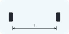
The unsupported length of screw between its two bearing supports.
- Unit
- mm
- Typical
- 300 – 1 500 mm
The critical speed falls with the square of this length: twice as long, a quarter of the speed.
Screw efficiency
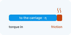
How much of the motor's work reaches the carriage; the rest is friction in the nut.
- Typical
- 0.9 for a ball screw, 0.3 – 0.5 for a trapezoidal thread
The torque for every force on the carriage is divided by it.
Supports
How the two ends of the screw are held: fixed (a pair of angular-contact bearings), supported (one bearing that lets the shaft tilt), or free.
- Typical
- fixed – supported for most axes
Stiffer ends raise the critical speed: fixed – fixed takes 2.3 times the speed of supported – supported, and fixed – free barely a third of it.

Nut preload
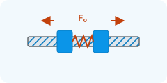
The force a preloaded nut presses on the screw with, to take out the backlash.
- Unit
- N
- Typical
- 0 for a plain nut; 5 – 10 % of the dynamic load rating for a preloaded one
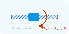
Preload adds a constant drag torque — small, but there in every phase.
Preload friction
The friction coefficient the preload drag is computed with: drag torque = μ₀ × preload × lead / 2π.
- Typical
- 0.1 – 0.3
Catalogues quote 0.1 to 0.3; 0.2 is a fair middle.
Coupling inertia
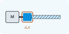
The inertia of the coupling between the motor shaft and the screw or the drive pulley.
- Unit
- kg·m²
- Typical
- 1 – 50 × 10⁻⁶ kg·m²
It turns at motor speed, so it counts as it is — no gear ratio in between. Type it as 1e-6 for 1 × 10⁻⁶ kg·m².
Screw inertia
The inertia of the screw shaft about its own axis.
- Unit
- kg·m²
- Typical
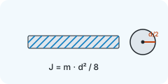
- a solid steel Ø16 × 500 mm screw: 2.5 × 10⁻⁵ kg·m²
Left blank, the page takes a solid steel cylinder of the given diameter and length, m·d²/8. The catalogue figure is usually a little lower — the thread is cut away.
Pulley pitch diameter
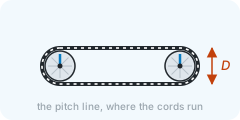
The diameter at which the belt's cords run — the pitch line — not the outer diameter of the teeth.
- Unit
- mm
- Typical
- 25 – 80 mm; from the tooth count, D = z · pitch / π
Every force on the carriage reaches the motor through half of it and every mass through its square: a bigger pulley asks for more torque and reflects more inertia, but turns slower for the same speed.
Belt mass
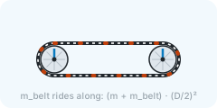
The mass of the whole belt loop: it moves at the carriage's speed and counts as inertia with the carriage, (m + m_belt) · (D/2)².
- Unit
- kg
- Typical
- a few hundred grams on a short axis; the catalogue gives the belt's mass per metre
It rides on no guide, so it adds no friction; its tension loads the bearings, not the motor. 0 if unknown — it is usually small next to the carriage.
Pulley width
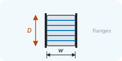
The width of each pulley, used only to estimate its inertia as a solid cylinder of the pitch diameter.
- Unit
- mm
- Typical
- the belt width plus the flanges: 20 – 50 mm
Type the pulleys' inertia from the catalogue instead when you have it; the estimate is then ignored.
Pulley material
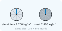
What the pulleys are made of, for the inertia estimate: aluminium at 2 700 kg/m³ or steel at 7 850 kg/m³.
- Typical
- aluminium for most axes; steel for small pulleys under high load
A steel pulley has 2.9 times the inertia of an aluminium one of the same size — on a direct-driven belt axis that is most of the mechanism's own inertia.
Pulley inertia
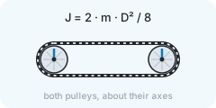
The inertia of both pulleys together, about their axes.
- Unit
- kg·m²
- Typical
- two solid aluminium Ø50 × 32 mm pulleys: 1.1 × 10⁻⁴ kg·m²
Left blank, the page takes two solid cylinders of the pitch diameter and width in the chosen material, m·D²/8 each. The catalogue figure counts the bore and the flanges and is a little different.
Belt efficiency
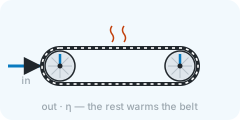
How much of the motor's work reaches the carriage; the rest is lost in the belt's flexing and the pulleys' bearings.
- Typical
- 0.9 – 0.98 for a toothed belt; 0.9 is the usual sizing value
The torque for every force on the carriage is divided by it; while braking, the load drives the motor through it instead.
Allowable belt force
The largest peripheral force the belt may carry, as its catalogue states it for the width, the pitch and the teeth in mesh.
- Unit
- N
- Typical
- from the belt catalogue, for the width and the pitch; blank = no check
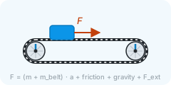
Step 3 compares it with the force the belt carries at the peak of the move — friction, gravity and the external force plus (m + m_belt) · a — and flags the belt when it is over. Leave it blank and no check is made.
The load, part by part
Everything that moves with the axis, one line each, so the total stays traceable.
- Typical
- carriage, workpiece, fixture, nut
On a linear axis the masses add up. On a rotary axis each part is an inertia, or a disc given by mass and diameter (m·d²/8).

Gearbox
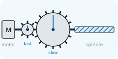
A reducer between the motor and the screw or the drive pulley: the motor turns faster and sees less inertia.
- Typical
- none for a direct-coupled screw; 3 – 10 : 1 for a belt axis or where the motor is small
The load inertia at the motor falls with the ratio squared — the usual cure for an inertia ratio that is too high.
Gear ratio
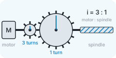
Motor turns per turn of the screw or the drive pulley — 3 means the motor turns three times while it turns once.
- Typical
- 3 – 10
Speed at the motor rises by the ratio, torque at the motor falls by it, inertia at the motor falls by its square.
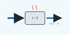
Gearbox efficiency
How much of the motor's torque comes out of the gearbox.
- Typical
- 0.9 – 0.97 for a planetary stage
Gearbox inertia
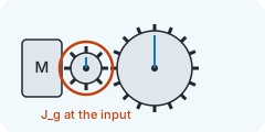
The gearbox's own inertia, as the catalogue states it at the input (motor) shaft.
- Unit
- kg·m²
- Typical
- 1 – 100 × 10⁻⁶ kg·m²
Type it as 1e-5 for 1 × 10⁻⁵ kg·m².