cyclogram
Motor sizing terms
The words of step 4 — servos, steppers, BLDC and AC induction motors, and the charts that judge them — each with what it means, its unit and what is typical. Try any of them in the calculator.
Motor Motor type Rated torque Peak torque Rated speed Maximum speed Rotor inertia Voltage Brake Hold with the brake Inertia ratio limit Holding torque Speed the torque holds to Safety factor Step angle Limited-duty torque Permissible load inertia Breakdown torque Base speed Motor files The speed–torque map Torque over the cycle
Motor
The motor that drives the axis: pick one from the list, or type a catalogue line in by hand and keep it under "my motors".
- Typical
- a generic 3000 rpm servo of 50 W to 3 kW to start; your own motors, saved in this browser; the catalogues later
The checks below the list say whether it makes the move, and with how much to spare.
Motor type
What sort of motor it is — the type decides what its numbers mean, the shape of its torque over speed, and which checks apply.
- Typical
- a servo for positioning; a stepper for small, cheap, open-loop axes; a BLDC motor for speed control; an AC induction motor on a VFD for big, slow axes
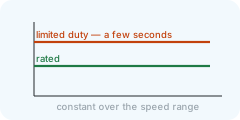
A servo gives its rated torque to the rated speed and its peak for a short while, at constant power above. A stepper holds its pull-out torque to a corner speed and loses it fast beyond; the page uses that torque over a safety factor and watches the duty cycle. A BLDC motor keeps its rated torque over the whole speed range, with a limited-duty torque for a few seconds. An AC induction motor on a drive gives its rated torque to the base speed and weakens beyond, its breakdown torque falling with the square of the speed.
Rated torque
The torque the motor can give continuously without overheating — the line the RMS torque is checked against.
- Unit
- N·m
- Typical
- 0.3 N·m (100 W) to 10 N·m (3 kW) at 3000 rpm
For a servo it is the rated power divided by the rated angular speed: P / (2π·n/60).
Peak torque
The torque the motor can give for a short while — the line the peak of the move is checked against.
- Unit
- N·m
- Typical
- about three times the rated torque
Above the rated speed it falls off; the page derates it at constant power unless the motor carries its own curve.
Rated speed
The speed up to which the motor gives its full torque.
- Unit
- rpm
- Typical
- 3000 rpm for most servos; 1500 or 2000 for big ones
Beyond it the available torque drops, roughly as rated speed over actual speed.
Maximum speed
The speed the motor must never exceed — mechanically and for its feedback.
- Unit
- rpm
- Typical
- 5000 – 6000 rpm
The move's top motor speed is checked against it.
Rotor inertia
The inertia of the motor's own rotor, as the catalogue states it.
- Unit
- kg·m²
- Typical
- 3 × 10⁻⁶ (50 W) to 6 × 10⁻⁴ (3 kW)
It sets the inertia ratio, load over rotor, which decides how well the servo loop can be tuned. Type it as 2.6e-5 for 2.6 × 10⁻⁵.
Voltage
The supply the motor and its drive are built for.
- Unit
- V
- Typical
- 230 V single-phase up to about 750 W; 400 V three-phase above
It does not enter the sizing; it is kept so the saved motor is complete.
Brake
Whether the motor has a holding brake — a spring-applied brake that holds the shaft when the power is off.
- Typical
- on vertical axes; off elsewhere
Needed on a vertical axis, so the load does not fall when the drive is disabled. With a brake, the dwell can be held by it instead of by the motor's torque.
Hold with the brake
During the dwell the brake holds the load, so the motor carries no torque then.
- Typical
- on, when the brake may be engaged during the dwell
That lowers the RMS torque on a vertical axis. Engaging the brake every cycle wears it; check the brake's cycle rating.
Inertia ratio limit
The largest load-over-rotor inertia ratio you accept.
- Typical
- 10 for standard servos; 5 for very dynamic axes; up to 30 with a stiff coupling and good tuning
Below it the servo loop settles quickly; above it the motor can only tune slowly or oscillates.
Holding torque
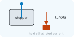
The torque a stepper holds at standstill with its rated current — the figure on the catalogue's first line.
- Unit
- N·m
- Typical
- 0.4 N·m (NEMA 17) to 8.5 N·m (NEMA 34)
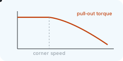
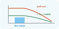
Its pull-out torque, what it gives while turning, starts near the holding torque and falls with speed; the page takes it flat to the corner speed and falling as 1/n beyond unless a curve is given, and uses it over the safety factor.
Speed the torque holds to
The speed up to which the stepper's pull-out torque stays near its holding torque; beyond it the torque falls away, roughly as that speed over the actual speed.
- Unit
- rpm
- Typical
- 200 – 600 rpm on a chopper driver; higher with more supply voltage
A catalogue's pull-out curve says exactly how; without one the page takes the corner from this field.
Safety factor
How much of the pull-out torque a stepper is allowed to use: the move's torque times this factor must stay under the pull-out curve.
- Typical
- 2; 1.5 for a well-known load
Open loop forgives nothing — a stall is a lost position — so steppers are sized with twice the torque they need.
Step angle
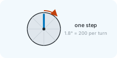
The angle of one full step; with the speed it gives the step rate the driver must deliver.
- Unit
- deg
- Typical
- 1.8° (200 steps per turn); 0.9° for fine steppers
It does not change the torque the page computes — it is shown with the pull-out check as steps per second, the unit catalogue curves are drawn over.
Limited-duty torque
The torque a BLDC motor's controller allows for a short while — starting, accelerating — before it limits the current.
- Unit
- N·m
- Typical
- 1.5 – 2 × the rated torque, for a few seconds
The peak of the move is checked against it; the RMS against the rated torque.
Permissible load inertia
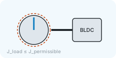
The largest load inertia the maker allows at the motor shaft for the controller to hold its speed through the ramps.
- Unit
- kg·m²
- Typical
- from the catalogue; blank = the ratio rule
Given, the page checks the reflected load inertia against it; blank, it applies the inertia-ratio limit instead.
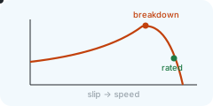
Breakdown torque
The most an induction motor can give before it stalls — the top of its torque–speed curve.
- Unit
- N·m
- Typical
- 2 – 3 × the rated torque
The peak of the move is checked against it; above the base speed it falls with the square of the speed, and the drive's own current limit may sit below it.
Base speed
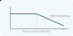
The speed the motor reaches at its rated frequency, just under the synchronous speed; up to it the drive gives full torque.
- Unit
- rpm
- Typical
- 1 400 – 1 450 rpm for a 4-pole motor at 50 Hz (1 750 at 60 Hz); 2 900 for 2-pole
Above it the drive weakens the field: constant power, the torque falling as base speed over actual speed.
Motor files
Your own motors as files: drop them here and they join "My motors" in this browser; download the list to keep or share it.
- Typical
- one JSON file per motor, or a CSV with one motor per row; a whole folder at once
A JSON file holds one motor or a list, with the page's field names (ratedTorque_Nm, peakTorque_Nm, ratedSpeed_rpm, maxSpeed_rpm, rotorInertia_kgm2, voltage_V, kind, name, maker …); a CSV has those as column headers, with common spellings understood. A folder is read through, file by file; one with the same name and maker replaces the saved one.

The speed–torque map
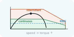
What the motor can give at each speed, and what the move asks of it at each speed.
- Typical
- the move's peak inside the orange field, its RMS line inside the green one, with the margins step 4 asks for
The green field is the continuous region — torque the motor holds for ever without overheating; the RMS of the cycle (the dashed blue line) must stay inside it. The orange field is the intermittent region — torque for a short while; the peak of the move must stay inside it. Both fall off above the rated speed. The black curve is the move itself, speed against torque, its peak marked by a dot; the blue dot is the moment the drawing is at. For a stepper the orange line is the pull-out torque and the green one that torque over the safety factor; for an AC motor the orange line is the breakdown torque, for a BLDC motor the limited-duty torque.
Torque over the cycle
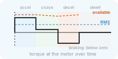
The torque the motor must give at every moment of the move and the dwell.
- Typical
- a step up while accelerating, a small constant torque while cruising, a step down below zero while braking
The shaded fields are the phases: accelerating (blue), cruising (green), decelerating (orange), dwelling (grey). Where the black curve dips below zero the load drives the motor — it brakes — and that is the energy step 5 counts. The dashed orange line is the intermittent torque available at that moment's speed; the dashed blue line the RMS over the cycle, which the rated torque must cover.