cyclogram
Pneumatic cylinder terms
The words of a cylinder's steps 2 and 4 — the cylinder, the air that drives it and the checks that judge it — each with what it means, its unit, what is typical, and a short animation. Try any of them in the calculator.
Bore Rod diameter Supply pressure Air flow to the cylinder Tube length Tube inside diameter Flow control Valve delay Cushioning Load ratio
Bore
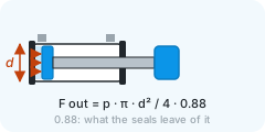
The inside diameter of the barrel — the piston's diameter. The force out is the pressure on the piston's area: F = p · π · d² / 4, of which the seals leave about 88 %.
- Unit
- mm
- Typical
- 12 – 100 mm; ISO 15552 sizes 32, 40, 50, 63, 80, 100
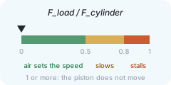
A bigger bore pushes harder but fills with more air each stroke, so on the same flow it strokes more slowly. The right bore is the smallest whose load ratio stays under 0.5.
Rod diameter
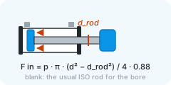
The diameter of the piston rod. On the retract the air pushes only on the ring around it, so the force in is smaller than the force out.
- Unit
- mm
- Typical
- blank = the usual ISO rod: 12 mm for a 32 bore, 16 for 40, 20 for 50 and 63
Leave it blank and the calculator takes the usual rod of an ISO cylinder of that bore; type it for any other cylinder.
Supply pressure
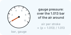
The gauge pressure at the valve — what the regulator's gauge reads, above the atmosphere around it.
- Unit
- bar
- Typical
- 6 bar is usual; 4 – 8 bar in most factories
The force rises with it, and so does the air each stroke takes: the barrel's volume times (p + 1.013) / 1.013 in litres of free air.
Air flow to the cylinder
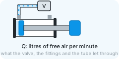
How much air reaches the cylinder per minute, in litres of free air at atmospheric pressure — the least of what the valve, the fittings and the tube let through.
- Unit
- l/min
- Typical
- 100 – 1 000 l/min of free air, from the valve's rated flow
The stroke time is mostly the air the stroke needs divided by this flow. A valve's nominal flow, measured at 6 bar with a 1 bar drop, is an upper bound; long thin tubes and small fittings lower it, and the calculator does not model them — fold them into this figure.
Tube length
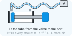
The length of the tube from the valve to the cylinder's port.
- Unit
- m
- Typical
- 0.5 – 3 m; 0 for a valve on the cylinder
The tube fills and empties with every stroke, so its volume adds to the air each stroke needs and to the time it takes. Its flow resistance is not modelled — a long tube also lowers the air flow.
Tube inside diameter
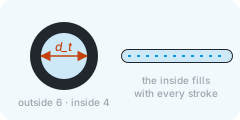
The inside diameter of the tube, not the size it is sold by — tubes are named by their outside.
- Unit
- mm
- Typical
- 4 mm inside a 6 mm tube, about 6 inside an 8, about 7.5 inside a 10
With the length it gives the tube's volume, π · d² / 4 · L, filled with every stroke.
Flow control
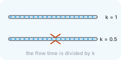
The share of the air flow the flow-control valve lets through: 1 when it is open, less as it is turned in.
- Typical
- 1 = fully open; 0.3 – 0.8 when a throttle slows the stroke
Throttling the exhaust is how a cylinder is slowed and smoothed. The flow time is divided by it, so 0.5 doubles it.
Valve delay
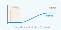
The time between the signal and the piston starting to move: the valve switching, and the pressure building until the piston breaks loose.
- Unit
- s
- Typical
- 0.02 – 0.1 s with the control's own response
It is added to the stroke time and drawn as the pale band at the start of the chart in step 3.
Cushioning
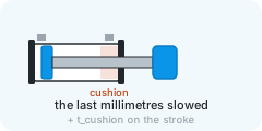
The extra time the end cushion takes: the last millimetres of the stroke are slowed so the piston does not strike the end cap.
- Unit
- s
- Typical
- 0.02 – 0.1 s; 0 without end cushions
Adjustable cushions trade time for a softer stop. It is added to the stroke time and drawn as the slowing at the end of the stroke.
Load ratio
The force the load needs divided by the force the cylinder makes at this pressure, after the seals' share.
- Typical
- under 0.5 for a quick stroke; 0.5 – 0.8 slows it; over 0.8 it can stall
Under 0.5 the air, not the load, sets the speed. Above it the stroke slows — the calculator stretches the flow time by 1 / (1 − ratio), an empirical model, indicative above 0.5 — and above 0.8 it crawls and can stall. At 1 or more the piston does not move at all.